Idea
The core idea is to perturb the video output of a game system using analog components and capture the video feed. That way when the button is pressed, we can see it in the video footage and count the number of frames until the reaction. This idea was first applied by noodalls.
The following picture displays four frames of the video feed we are able to capture.
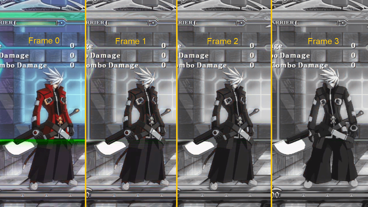
On frame 0, the button is pressed, making the video feed black and white after 67% of the screen being displayed. We
know that the button was pressed exactly 10.8ms after the vsync. Now we can count. On frame 3, the character is
starting to move. Therefore, in this instance we can say that for an in-frame timing of 11ms we have two frames of
additional lag.
Metrics
There are two metrics that are computed in this methodology:
inputlagis the average amount of time between the input and the beginning of the reaction frame.stabilityis the probability of getting the same input lag for the same in-frame timing.
Due to the way inputlag is defined, in the previous example its value would have been 2.3 frames. While it might seem
unfair because in a vsync environment, it is impossible to react before the next frame. However, this is accurate to
what the user feels and secondly it shows exactly when the game polls for new data.
The resulting graph that you can get is the following.

The blue squares indicates where the input has been measured, to more the blue is pronounced the more certain the lag is going to be this value. The line plot is the average lag it represents. In this case, around the 14th milliseconds, we can see that the game is reading its inputs. The stability here is nearly perfect, the only time that the outcome is not clear is around the 14th milliseconds again (to be expected because this was made using a USB device which has ~1ms of lag ±0.5ms).
Hardware Setup
The interruption device
Warning: this requires some basic electronic knowledge.
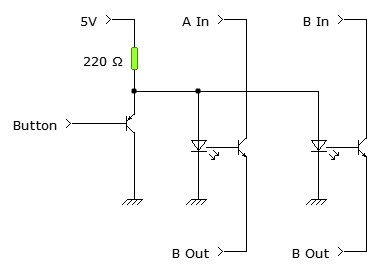
You need to build a small electronic circuit that is able to interrupt an analog video signal. We have had successful results with either a 74HC4053 (2-channel analog multiplexer), or like depicted in the schematics here using optocouplers.
Usually, only two channels are necessary to have a usable interruption as we will see in later sections.
This is far from perfect as you may experience some color changes compared to the original video feed without pressing a button. But the goal is to measure lag not having accurate colors and this costs basically nothing.
The video conversion and capture
The interruption device works only on analog video, however modern devices only output HDMI. Fortunately, it is possible
to convert this signal into a YPbPr signal (aka. component video) for a small cost. We have been using the Portta
HDMI converters that noodalls has proven to be completely
lagless.
Then, you must have a video capture device able to handle the native resolution and frame rate of your device. Fortunately, a lot of capture cards still support component input.
The input device
If you need a USB controller, then you absolutely need to make sure that your device is very fast and very stable. Most of the measures we have performed were done using a Brook Universal Fighting Board which is the fastest we know of (~1ms). You also obviously need a controller that has a common ground PCB that you can access to easily.
Obviously, if you can poll the controller as it is read by the target device (like the JAMMA port or the pin of a NeoGeo DB15) this is better.
The setup
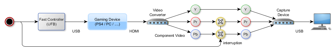
Here is an example of a completed setup with everything in place for a USB+HDMI system (modern console or PC):
The experimentation protocol
1. Setup your interruption chain
We have detailed that in the previous sections. Here are the signal you need to interrupt:
- If you are using a component video signal, interrupt
PrandPb. This will turn the screen black and white if interrupted. - If you are using a RGB stream (SCART or VGA), interrupt one of the color. Note: you can use two channels in parallel for one color to avoid disturbing the impedance too much. Make sure that this color is abundant in the scene to properly make the detection.
Connect your button signal to the button you wish to measure.
2. Game setup
Launch the game you want to measure. Please yourself in a situation that most ensure those conditions:
- The image is mostly static during all the test. If you can use a mode like a training stage or a section without enemies this will make your life way easier down the line.
- The reaction you expect will be roughly in the same place on every test.
- The button that you press has no gameplay lag to account for (some moves may have a buffer).
It is still possible to make measures without all conditions met, it's just harder to automate.
3. Configure the video recording
You have to have a video record without any stutter in the natural resolution and frame rate.
To help you on this, a program has been made to able to do just that. It is part of the inputlag toolset.
4. Press record and push the button plenty of times
By experience, a set of 300 points is the minimum for a decent measure. This usually corresponds to 5min of button presses.
Make sure that:
- You press the button firmly without hesitation
- Wait for the previous animation to be clearly finished before pressing the button again
If you don't adhere to these two rules, you will regret it during analysis.
5. Analyze the video feed
Firstly, you need to make sure that your video feed has a good quality. Open the file in VLC, then using the frame-by-frame
navigation (using the e key): find an interruption, and count until you find the reaction frame. This will give you
a first estimation.
To have a complete picture of the results, you need the inputlag toolset. This will analyze the video feed and will output a three-column data file: the frame, the scanline of the input, and the number of frames until the reaction frame.
This tool will automate the analysis. However, it needs to be configured on each video feed. The instructions are provided in
the README of the tool. Here is a general process to gather clean results:
- Select the right algorithm for your use case
- Execute the analysis in debug mode (
-d) and a very large threshold (-t 1000) - Check that the button is properly detected (ping me if it is not)
- Tune the
-x -X -y -Yoptions to select only the interesting part of the feed. Restart the analysis until you have the right parameters. - Advance the frames and look at the console for the right threshold value
- Test that your settings work properly on a few examples
- Deactivate the debug mode and check for any unusual values
- If there are, check that your settings are correct using the
-soption to jump directly to the problematic frame - Repeat until you have a good csv
You may still have a few faulty measures due to the previous conditions not being met. You can still clean them afterwards.
6. Analyze the result
To do that, you may import the produced csv in a spreadsheet software. Then, group your scanlines by groups of 60
(that's the default used on the results section). And finally, create a pivot table with the grouped scanlines and the
reaction frames.
Vsync Off
The results are way more fair on vsync because this setup is definitely able to detect vsync while it is not (currently)
capable of detecting the frame buffer flip. I have a few experiments but it is not ready yet.
Without vsync, the stability will be obviously impacted because if the buffer flip is done at the end of the frame, it
will be impossible to detect the reaction frame before the next vsync.
Comparison with camera-based measures
The main alternative method is filming the screen with a high-speed camera. There are a few issues in this method:
- It uses a screen which may have lag
- Low-cost high speed camera are 240fps which is only 4x the screen refresh rate
- This method can only measure the
displayed input lag, the game engine input lag as we define it is the lag between the input and the beginning of the reaction frame.

Thus, it is normal if the input lag measured using the camera-method is a frame slower
Comparison with sensor-based measures
The sensor method is an improved way of measuring using the camera-based measure. It requires a bit of hardware to measure the light quickly and some software to fetch this data and measure it against the actual value.
Two main devices come to mind in this category, the Ben Heck's Controller Monitor Rev 2, and the NVIDIA LDAT (similar to NVIDIA Reflex methodology). The idea is simple on paper:
- Hack an input device to have the wire connected to the button.
- Put a light sensor on the screen.
- Connect both to a small micro-controller that will report the value for both.
- Measure the time difference between input and luminance change.
When it comes to comparison with the presented method here we have the same issue as the camera-based measure: display lag is included. So, it has to be taken into account in the final result and position of the sensor matters a lot for a sub-frame result.
Furthermore, this method has the issue of requiring a big luminance change on the situation you want to measure. If you are a game developer, you can modify the game to display a large white/black rectangle. Otherwise, you have to find an animation that triggers the flicker needed (like a gun fire).